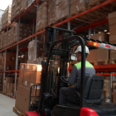
Solids and water are the most dangerous contaminants in lubrication and hydraulic systems.
Mineral and synthetic oils have a temperature-dependent water saturation point. If this point is exceeded, free or emulsified water develops.

Effects of contaminants in lubricating oil and hydraulic fluids

Saturation limit for water in hydraulic fluid
Water in a hydraulic system:
- Encourages component corrosion,
- Carries the risk of pump cavitation,
- Increases friction and wear, and
- Damages elastomers and synthetics.
Free water should be separated from fluid in the tank as quickly as possible and removed by an appropriate drainage device. Contamination of watery cooling lubricants in the hydraulic system, particularly on tooling machinery, can lead to the formation of sticky residue upon evaporation of the water content, which can result in pump, valve, and cylinder destruction. Hydraulic fluid should release any water that infiltrates as quickly and as completely as possible (water separation capacity, WAC).
Additives present in the fluids react with free water. Oxides, acidic sludge, and resins form as a consequence. There also exists the risk of the free water freezing in systems that operate below freezing point.
The resulting ice crystals generated can compromise function of the overall system and lead to failure.
The water content in hydraulic fluid should not exceed 0.12% or (1200ppm). Oil conservation measures should be taken for a water content beyond 0.1% (1000ppm).
Causes include:
- Worn out piston rod seals,
- Open tank inlets,
- Formation of condensation water due to extreme temperature fluctuations,
- Heat exchanger leakage, and
- Incorrect machinery cleaning such as use of steam cleaning that can force steam into the tank via the aeration filter.
Damage patterns include corrosion of metal parts such as the inner tank walls, increased abrasive wear, bearing damage, breakdown of additives, changes in oil viscosity, and sludge formation.
Three forms of water in operating fluids
Water can be present in operating fluids in three forms dependent on additives and mechanical loading of the fluid. These forms are free water (visible to the eye), emulsified water, and dissolved water.
Dissolved water is referred to when water is present as one phase, with the hydraulic media.
Free water is usually present in a different phase due to density differences between hydraulic or lubricating media and water. Its presence is made evident through a clouding of the fluid. Water droplets related to this clouding are 2-10μm in size.
Water in hydraulic media, based on mineral oil, collects at the bottom of the tank while water in the phosphate ester and chlorinated hydrocarbon separates at the media surface due to the low specific weight of the water.
The comparison with air is more clearly understood:
Rain is a free, mist emulsified water in the air. The humidity in clear, transparent air is dissolved water.
Free water that is not released forms an emulsion, for example, when travelling through pump passages or valves whose stability is influenced by the various degrees of surface and boundary surface tension of the respective medium.
Surface tension is a measurement of the capacity of a medium to take on the form of the smallest possible surface. In the boundary surface between two non-mixable fluids, as is normally the case with water and hydraulic media, shearing stresses form, whose height is a gauge for the greater or lesser degree of stability of the previously formed emulsion.
When the so-called boundary surface tension is high (over 0.035N/m), then the medium exhibits good demulsibility. However, if the boundary surface tension sinks below the value of 0.02N/m, then the emulsion is too heavy or not separable at all.
Emulsions become more stable on the one hand through the admixture of different additives and inhibitors (desired effect) and, on the other hand, through the presence of oxidation products, solid contaminants, and rust (undesired effect). High viscose fluids fundamentally exhibit a worse water separation capacity than low viscose fluids.
A so-called saturation limit is established for each hydraulic medium, which is the maximum concentration of water that can be dissolved in the hydraulic medium under atmospheric conditions.
Changes in ambient conditions such as pressure or temperature influence the saturation limit.

Typical water concentration, albeit system dependent
Sinking temperatures cause dissolved water to initially re-separate itself in the form of finely distributed droplets and subsequently it completely separates from the operating medium.
Water content determination
In the system (online procedure):
Water content in operating fluid can be determined by means of water sensors using an online procedure.
Free and emulsified water can be satisfactorily determined online using capacitive measuring methods in the oil.
A quick and accurate on-site analysis is possible using the hydrogen gas method. For this, an oil sample must be taken from the operating system. Through the addition of calcium hydride and oil, a rise in pressure takes place in a reaction vessel. This rise in pressure can be read as the potential water content.
In the laboratory (offline procedure):
There are various methods for the determination of water in the hydraulic medium. These include the visual method, the crackle test method, and the Karl Fischer method according to DIN 51777.
Visual method
The visual method is based on the fact that a hydraulic medium with a water content above the saturation limit becomes cloudy. Yet such cloudiness can also be the result of air and dirt present in the medium.
Crackle test method
Some oil sample drops are dropped on a hot plate of approximately 130°C in the crackle test method. This causes the oil and water to separate. The water dances in droplet form on the hotplate and causes a crackling noise. This test can only be applied with free and emulsified water. In practice this test is usually used to relate the cloudiness of the oil to a definite increase in water content.
Karl Fischer method
Determination of the exact amount of water content is usually carried out in a laboratory using the call Karl Fischer method according to DIN 51777.
The water is forced out of the fluid by heating a small quantity of oil Dried nitrogen guides the moisture into a titrating vessel. The water reacts electrochemically with the Karl Fischer solution in the vessel. The water content is precisely determined via the point of inflection on the titrating curb.
The water content in the fluid sample being tested responds proportionally to the consumption of Karl Fischer solution: a solution of iodine ions, sulphur dioxide and further additives.
Practical meaning of water content determination
The water content in a lubricant should not exceed a specified allowable value, dependent on oil type and oil application. Too much water in oil can cause corrosion, cavitation and or oil oxidation, as examples.
If the water content is below the saturation limit, meaning it is dissolved in the oil, it has no effect on the useful life of the lubricating or hydraulic fluid. Only with transformer oils can the disruptive voltage, which is important for transformer insulation, be influenced.
Water quantities above the saturation limit can be detected by the cloudiness of the oil. As such quantities of water are practically not soluble in oil, phase limits always form.
A classic operating fluid releases infiltrating water quickly. Since small amounts of water (up to approximately 1 Vol.-%) can form over weekend downtime, a type of HLPD operating fluid with limited emulsifying characteristics is often used. A small amount of condensed water should be stably taken in over the short term, but larger amounts of water should be separated quickly.
For some years operating fluids have been used for specific application scenarios (tooling machinery with cooling lubricant access to operating fluid, submarine hydraulics), which can stabilise more than 5 Vol.-%) of water. In addition to the usual ‘L’ and ‘P’ active substances for the operating fluid, they also contain dispersant/detergent additives. The latter act in such a manner that the operating fluid can stably take in water as well as aging and contaminant constituents.
Both solid and watery contaminants are taken in by these detergent/dispersing acting (HLPD) hydraulic fluids and they are finally distributed and held in suspension in the hydraulic medium. In this manner they can be filtered out by means of a suitable filter system without the hydraulic function of the equipment or being negatively influenced.
Water separation capacity
Oil examined to determine water separation capacity (WSC) is subjected to a flow of steam at 65°C for 20 minutes.
The volume of steam is measured by means of condensate forming in the oil. After stopping introduction of the steam, separation of water from the oil by the sinking of the boundary surface between the oil and water is observed. The length of time required until the separation is completed is recorded.
The ASC is degraded through mixing contamination and oxidation. If water enters steam turbine oil or circulation oil systems in paper machines or heated calendars due to leakage, for example, it must be completely removed in a short amount of time.
This can take place vial the following measures.
Separation of water content via tank breathing
Small amounts of water can be separated by means of tank breathing. In this process, the use of an aeration dryer is sensible: ambient air flows over a molecular screen or silica gel, is dried up and filtered in the tank.
By warming the air at the oil surface, relative moisture and a small amount of water are taken up in the air. This moisture enriched air is then removed via the aeration filter during the machine cycle.
Separation of small amounts of water with filter elements
In addition to particle separation, water absorption layers can be fitted into the filter element. The simplest water absorption layers consist of cellulose fibres. This fibre takes in free water much like a sponge. The application of a super absorber in the filter element is more beneficial. In this system, the water is transformed to a gel and cannot be removed from the filter again, even with an increase in pressure.
Saturation of the filter element with water is indicated by a rise in differential pressure.
The water absorbing filter elements are usually installed in the bypass circulation system with a constant volume flow and serve to separate particle contaminants through the combined use of micro-filter layers.
The separation process is recommended only when a small amount of water is expected such as with high air humidity or consistently high temperature fluctuations (or changes) in the operating fluid.
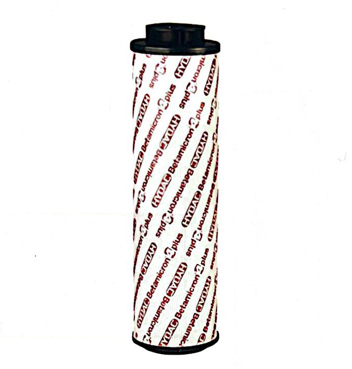
Element with super absorber for binding free water droplets
Boiling
Another method of separating water from oil is by boiling the fluid. System temperature is raised and tank aeration is increased by opening the tank cover during this procedure.
It must be considered, however, that considerable amounts of contaminants can access the fluid whereby the oil aging process is accelerated. An increase of temperature from 50°C to 60°C doubles the aging rate of the oil. An increase of temperature above 80°C doubles the aging rate again. This procedure is used very rarely and only under unusual circumstances.
Separation of large quantities of water
When the system is subjected to the continuous infiltration of water or process steam there are three further possibilities for separation.
Centrifuging
This expensive process sees water separation take place based on the density difference between water and oil.
Advantages include:
- Rapid separation of larger quantities of water
- Extraction of process water additives
Coalescence
The term coalescence is understood as the uniting of many small, finely distributed water droplets into large water droplets by means of special coalescing elements.
In the process, the water is stored in the fine fibres of the coalescing elements and is conveyed further into the coalescing element by the fluid flow. It is separated in the coalescing element from fluid by means of a special hydrophobic webbed fabric.
Large water droplets form sediments in a relatively short amount of time and, in operating fluids with lower density than water, they can settle on the tank floor. They rise to the surface of the operating fluid where they can be removed or drained in operating fluids with a higher density than water.
It is important to ensure that the specified pressure difference is not exceeded in this process. Viscosity must also be considered to ensure fault-free operation.
The maximum viscosity for an effective water separator is approximately 68mm2/s. The fewer emulsifying additives in the operating fluid the less the coalescence.
Vacuum evaporation principle
The vacuum evaporation principle is based on the fact that the boiling point of water is lowered under negative pressure and temperature reduction.
The process is used in a bypass flow. Oil flows into a vacuum chamber and it is finely distributed by injectors or nozzles. Air is guided through the oil fill charge in an opposite flow direction. When the air reaches the vacuum chamber, the relative humidity decreases due to the lowered pressure and the air temperature adapting to that of the oil temperature. The air becomes more hydro- receptive and removes water from the oil.
The water saturated air is transported to the surrounding environment by means of a vacuum pump. This procedure provides for the removal of free, emulsified and dissolved water. A residual water content of a few ppm can be achieved.
Advantages include:
- Separation of free and dissolve water,
- Suitability for mineral and rapidly biodegradable oils as well as fire resistant fluids
- Oil that is simultaneously dewatered and degassed.
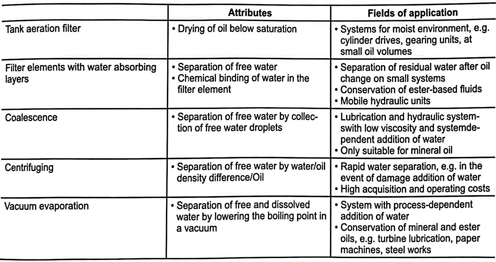
Summary of the most important dewatering processes
For more information call HYDAC Australia on 1300 449 322 or visit hydac.com.au/contact-us.html to send a message.